
Return to main page
Background for beginners
What I did last summer
Skills and Experiences
More info (for experts/collaborators)
What's next?
Philippa Young
Designing an Analogue Low Pass Filter System for a Quantum Ion Trap.
Research and Specifications
Low Pass Filter Research 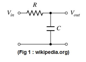
A simple low pass filter consists of a resistor and capacitor. The signal would be applied to the Vin rail and the Vout rail is then connected to the D-connector. This D-connector has a wire running to the trap electrode.
A simple representation of this can be seen in Fig.1.
For this basic low pass filter the cut off frequency (defined as the point where the magnitude of the signal has fallen by 3dB) can be calculated using the following equation:
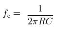
where fc is the cut off frequency, R is the resistor value and C is the capacitance.
Specification
In the case of the initial 6 filters the filter needs to allow 10kHz to pass through and have a signal of 10-4 by 100kHz. As this is not an extremely sharp cut off (less than 1db/octave) a simple low pass filter should be perfectly sufficient.
The filter box must have 2 50way D-connectors, which line up with the D-connectors on the vacuum system.
The 6 filters must be attached to pins 16, 34, 70, 72, 84 & 94.
Calculating the component values
Using the equation above would give the 3dB frequency, however in this case I have been given a starting and finishing voltage ratio. In this case the following equation can be used:
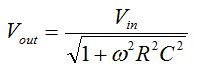
where we take Vout to be 1x10⁻⁴, Vin to be 1 and ![]() to be
to be ![]() (where f is the point where the frequency begins to cut off)
(where f is the point where the frequency begins to cut off)
This gives several possible combinations of values for R and C but the values I will use are:
R=220 ![]()
C=0.22
![]()