Detailed Information for Collaborators (or other Experts in the field)
The majority of the information for experts/collaborators can be found in the pages on my role in this group, however some subjects have been skimmed over and so more in depth details can be found here.
Improving the roll of speed and the effect ripples
There are various ways to improve the roll off speed of a filter, the most obvious being to use a higher order. One way to maximise the roll off speed is to allow what is known as a ripple in the pass band; this can be seen in Chebyshev type I and Elliptic filters. It appears as a wave in the pass band and the size can vary the filter roll of speed dramatically.
Ripples can range from 0.01dB to around 5dB with a minimal effect on your filter system. In our case the size of the ripple is ideally going to be quite small as when shuttling an ion it is useful to know exactly how much of the frequency is getting through to the trap.
The effect of ripple size is that the bigger the ripple the steeper the curve so the less orders you will need.
When the software comes up with values for the optimum filter it uses component values to up to 3 decimal places, obviously it is not possible to get the exact values the packages suggests, however it is possible to change the values manually to values which you can obtain and then refresh the graph.
In order to minimise the ripple I altered the values of the components in various combinations and zoomed into the pass band of the graph to compare the sizes of the ripples.
The resistor values do not effect the ripple size so it is only the capacitors and inductors which will need to be optimised.
An example of the effect of ripples is the case of the Chebyshev type I. If the ripple is set to 0.01dB then a 9th order is needed to meet the specification. However if the ripple is set to 0.1dB then an 8th order can be used to meet the same specification.
Different responses have ripples in different places, for example; Chebyshev type I has a ripple in the pass band, type II has a ripple in the stop band and then Elliptic has ripples in the pass band and the stop band.
Filter polynomials
I mentioned that the filter component values are determined by a ratio taken from polynomials.
A simple example of this is the following table of Butterworth polynomials (taken from http://alignment.hep.brandeis.edu/Electronics/A2037/Filter.html):
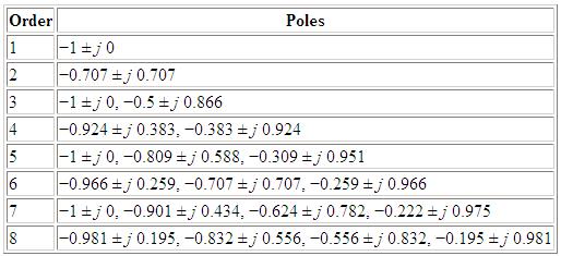
The coefficients of j are the values for the frequency ratio of that stage.
There is a detailed explanation of how the polynomials are used here
Q and Z in the passive filter design
When using AADE filter design, it asks for both Q and Z, in the simple explanation of how to use this package those were left out, i.e. the impedance, Z, was left to the standard value and the quality factor, Q, of the inductors was set to loss-less.
Obviously in terms of Q, an inductor can never be completely loss-less. Therefore the values of Q needs to be calculated.
This can be done by using the following equation:
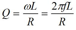
The value f corresponds to the resonant frequency of the inductor, this can normally be found on the data sheet from the manufacturer.
L is the inductance of the inductor and R is the resistance of the coil; again both of which can be found on the data sheet.
To find out what the impedance is before and after the filter you need to look at what circuit you have either side. If the impedance of the section before the filter is 20Ω then a 20 Ω resistor should be used at dipole 1. Whatever the value of the impedance after the filter is the value of the resistor in the final dipole position.
Purposefully using an odd ordered filter.
When I designed the filter using AADE filter design, the lowest order possible to meet the specification was 10th order, however this ended with a ‘block’ which had an inductor on the top dipole.
This meant that I had to increase the order to 11 as I couldn’t use a filter with an inductor on the end without a very large capacitor. This is because the next section of the circuit is the RF, which would mean that because there was no capacitor on the end, the filter risked becoming part of the RF filter.
Therefore an odd order was used because the last block has an empty space on the top dipole and only has a resistor and capacitor.