
Return to main page
Background for beginners
What I did last summer
Skills and Experiences
More info (for experts/collaborators)
What's next?
Philippa Young
Designing an Analogue Low Pass Filter System for a Quantum Ion Trap.
Research and Specifications
Research
The filters I built for the initial six filters were the most basic low pass filters you can use. In the case of the one hundred filters a more complex design would be needed to meet the specification.
When there are more than one resistor and capacitor in a circuit, the ratio of the cut off frequencies of each section of the filter can affect the behaviour of the filter. There are four main types of filter responses which can be utilised. These are Butterworth, Chebyshev type I, Chebyshev type II and Elliptic.
The following response curves show a typical cut off for each filter type. Please see explanations of each filter type and the basic terminology.
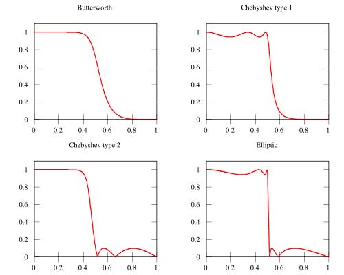
(Fig 1. The four most common filter responses. From Wikipedia)
The roll off of the filter can be improved by increasing the order number of the filter, i.e. by adding more ‘blocks’.
The following graph shows a Butterworth filter response for orders 1 through 5. The higher orders have a noticeably steeper roll off.
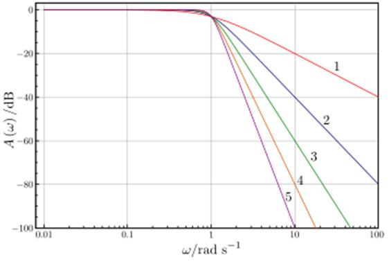
(Fig 2. The response curves of the first 5 orders of a Butterworth filter. From Wikipedia)
Active vs Passive
Filters can be active or passive. Active filters are created by using blocks of Sallen-Key circuits. The main difference in active and passive filters is that active filters contain op-amps as well as the resistors and capacitors.
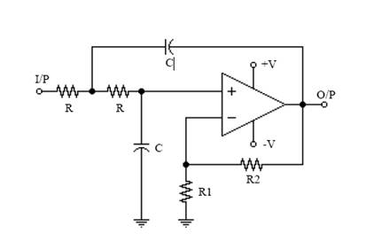
(Fig 3. A Sallen-Key circuit, the basic building block of most low pass filter systems.)
Each block containing one op-amp (as seen above in Fig 3) is two orders. For example a fourth order circuit would consist of two of these Sallen-Key circuits. In order to create odd numbered filters you can simply include a 1st order active filter as shown in Fig x, so that a 5th order filter would look like Fig 4 below.
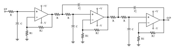
(Fig 4. A 5th order low pass Butterworth filter.
Fig 3 & Fig 4 are both based on the Sallen Key designs found at http://www.freeinfosociety.com/electronics/schematics/audio/butterworthfilter.pdf
In order to calculate the values of the frequencies cut offs for each block you need to use polynomials; Chebyshev or Butterworth. These will give a ratio of each block, so from there you can find combinations of resistor and capacitors which will give each block that frequency.
Data is available for the values of all the polynomials and orders in filter handbooks. Some I found useful can be seen in this list of useful resources.
The Following table shows the advantages and disadvantages of each filter type.
Filter Type |
Advantages |
Disadvantages |
Butterworth |
|
|
Chebyshev I |
|
|
Chebyshev II |
|
|
Bessel |
|
|
Elliptic |
|
|
Passive filters are much simpler in that they only have resistors, capacitors and inductors. The also use the same polynomials to calculate frequency ratios.
To create a higher order filter you add another inductor and capacitor on the chain to form a ladder shape. For example Fig 5 shows a 10th order Chebyshev filter. An odd numbered filter is created by not having an inductor in the final block (in this case dipole 11 would be blank giving a 9th order filter)
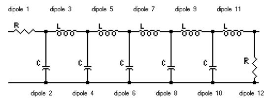
(Fig 5. A 10th order Chebyshev filter designed with AADE Filter Design V4.4)
The main advantage of using a passive filter is that there are far few components and they are in a much less complex shape. The circuit will therefore be simpler and so easier to design and manufacture.
Specification
Must allow 1MHz to pass through and block frequencies greater than 2MHz. Again the filter should block out to 10-4 which is an attenuation of -80dB.