
Return to main page
Background for beginners
What I did last summer
Skills and Experiences
More info (for experts/collaborators)
What's next?
Philippa Young
Designing an Analogue Low Pass Filter System for a Quantum Ion Trap.
Manufacturing
The strip board first needed to be cut to size and the edges filed to ensure there is no chance of any electrical short circuiting.
Holes for mounting the board need to be drilled into the board and the casing. The casing also needs D shapes machined out for the D connectors and holes to secure them.
The next step is to cut the tracks surrounding the screw holes to avoid shorts, and break any tracks which need breaking.
The capacitors can be soldered onto the correct strips. The resistors are soldered one leg to the stripboard and the second leg to the banana connector. A small piece of wire then goes from Vout to the D-connector pin.
Once the circuit is soldered and all the banana connectors and D-connectors are in the casing the ground can be attached joining the middle strip to the metal case.
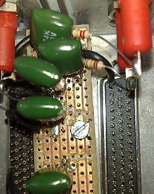
The photos below show my finished filter box.
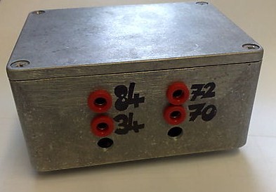
(View of the side of the filter box, showing connectors to pins 34, 70, 72 and 84. The lower two holes were intended for pins 16 and 94 however they would have blocked the screws for the D-connectors so they were relocated to the other side of the box.)
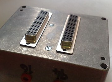
(The D-connectors on the bottom of the filter box attach the filter to the D-connectors on the vacuum system. Each of the 100 pins is connected to a receptacle on the chip bracket. The positions of the D-connectors must exactly line up with the vacuum system so distances were measured as accurately as possible)
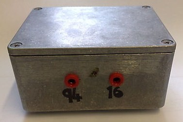
(The final two filters are on the opposite side of the box. The hole in the box for the ground wire to be fixed into can be seen between the two connecters)
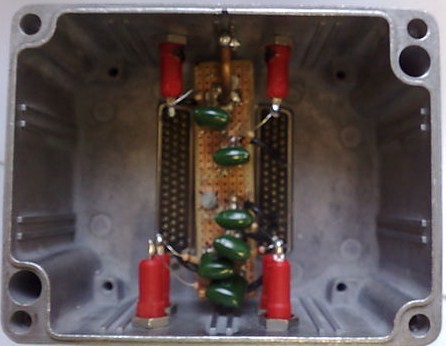
(Top view of the finished circuit board mounted in the casing.)
 _
_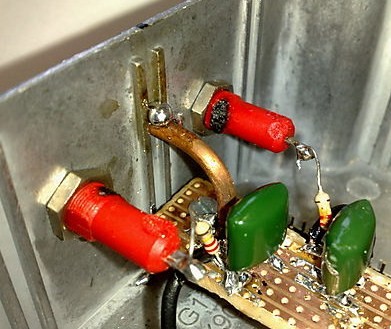
(Left image: Tracks around the screws are cut to avoid short circuits, resistors are soldered directly to the banana connectors, the edges of the circuit board are visibly filed on an angle so that there is no copper around the edge which might cause a short circuit. Right image: Ground wire is soldered to the central strip of the board and inserted into a hole in the side of the casing to ensure a secure connection. It was heated with a blow torch so that solder could be used to attach it to the box and the board for extra security.)