Return to main page
Filter Wiz Pro V4
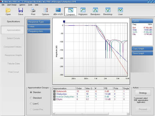
First the specification is input, these values are self explanatory, press calculate and it will see if there are solutions to your specification, if so click Proceed.

The next step is to choose your response type, the graph presented will show all possible responses in different colours, select whichever is most appropriate and click Proceed.
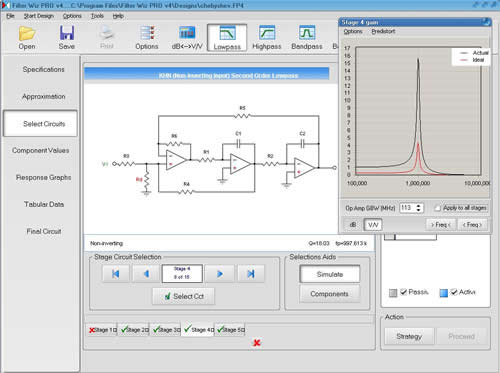
In the next step you have to select which topology you want to use (topology is just a term to describe which circuit you are using, normally named after its inventor, eg Sallen Key)
Once each circuit is selected you can tune the op amp gains to give the maximum effect. This is done by increasing the gain until the black and red lines are identical. When this is done for each stage of the circuit click Proceed.
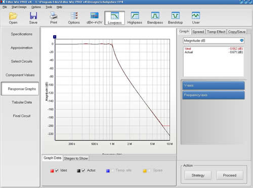
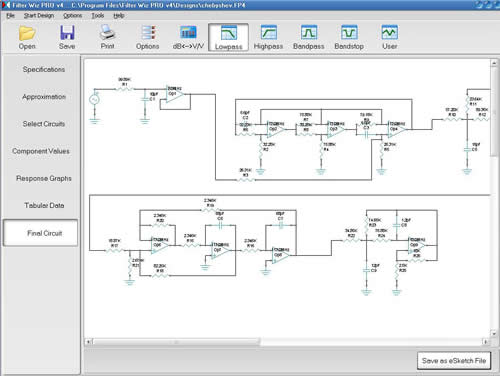
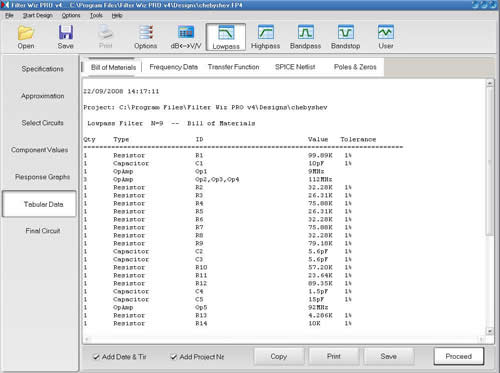
The program then outputs a list of parts, a response curve and a circuit diagram for the filter. As can be seen in the following images.
<< Go Back to Simulating filters
To design a passive filter using AADE first select: Design> Chebyshev
Select Low Pass and click OK.
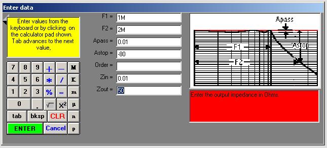
The following data must then be input:
Start frequency: The frequency which you want to pass through the filter.
End frequency: The frequency you want to end at and block out.
Pass band ripple: in dB, how much of a ripple is acceptable?
Stop attenuation / order number: Only one can be specified, in the case of stop attenuation it is what dB of signal can get through the filter. If you specify order number then it will design a filter of that order regardless of the stop band attenuation.
Impedance in / out: These will be dependant on your circuits at either end of the filter and only effect the values of the two resistors in the design.
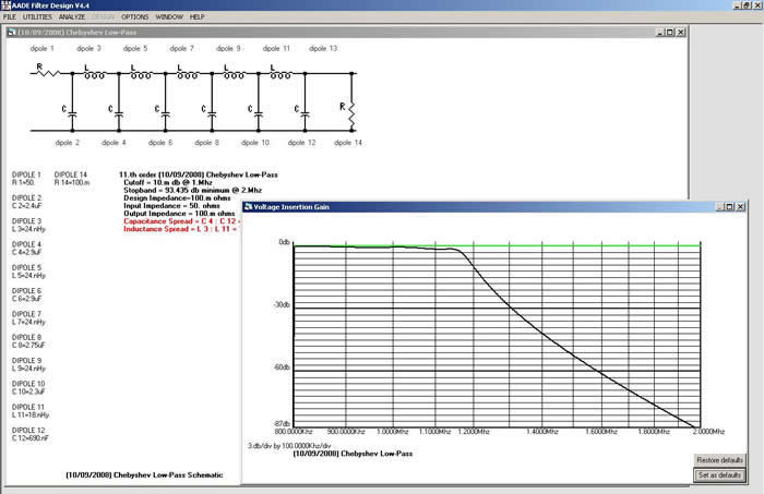
Click Enter. The circuit and component values should now come up.
To see a graph of the response of your filter select: Analyse> Voltage insertion gain, enter the max and min values you want on your axes and click Enter.
That’s all there is to do for passive filters!
<< Go Back to Simulating filters
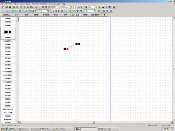
To start with choose the required components from the lists and position roughly where they should be according to the circuit diagram.
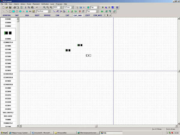
Create a net by clicking on the pads which should be connected together.
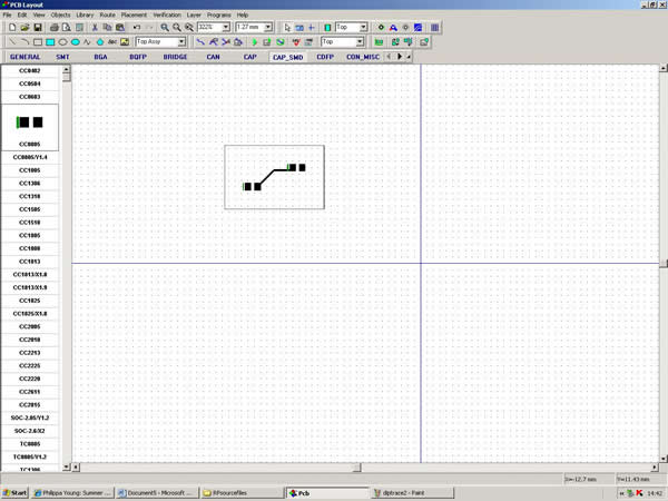
When you then click auto route the software will automatically work out the best way to connect all the components.
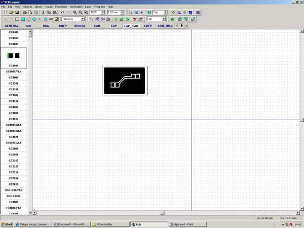
As ground is important in filters it is then a good idea to create a large area of copper fill, by using the copper fill tool on the tool bar. This gives a larger area to connect the ground wire to.
The finished PCB design can then be printed onto transparency to be manufactured.
<< Back to PCB