Dr Phil Birch
ARM CMIS IIR filters

There seems to be little information on the web about using Matlab and ARM CMSIS IIR functions. In princple it should be easy to design a filter in Matlab and run it on an an ARM chip. Well it is, its just the information seems to be spread over a number documents.
The design steps are as follows. Use Matlab to design an IIR filter and export the filter to the work space. (Or use any other method but convert it to SOS form). The format the CMSIS is expecting is slightly different to Matlab. Here is an example bandpass filter:
            SOS =

                1.0000   -0.9417    1.0000    1.0000    0.1845    0.8716
                1.0000    1.7675    1.0000    1.0000    1.2434    0.9009
                1.0000   -1.7449    1.0000    1.0000    0.5365    0.8054
                1.0000    1.9538    1.0000    1.0000    0.9467    0.8240
                1.0000   -0.6225    1.0000    1.0000    1.3914    0.9702
                1.0000    1.6693    1.0000    1.0000    0.0035    0.9582
            G =

                    0.6502
                    0.6502
                    0.8174
                    0.8174
                    0.0694
                    0.0694
                    1.0000
Each row of SOS is a stage and the parameters as [b0,b1,b2,a0,a1,a2]
Note a0 is always one and is not needed. Looking at the
Biquad Cascade IIR Filters Using Direct Form I Structure page we see the formula for each stage is
y[n] = b0 * x[n] + b1 * x[n-1] + b2 * x[n-2] + a1 * y[n-1] + a2 * y[n-2], which differs from
Matlab's y[n] = b0 * x[n] + b1 * x[n-1] + b2 * x[n-2] - a1 * y[n-1] - a2 * y[n-2]. To correct
for this we simply mutliple a1, and a2 by -1. However, this also ignores the gain
on each stage. To correct for this multiply b1,b2,b3 by the stage gain value in G.
The new coefficent matrix that is in the correct format form CMSIS is now
  Coeff =

    0.6502   -0.6123    0.6502   -0.1845   -0.8716
    0.6502    1.1491    0.6502   -1.2434   -0.9009
    0.8174   -1.4262    0.8174   -0.5365   -0.8054
    0.8174    1.5970    0.8174   -0.9467   -0.8240
    0.0694   -0.0432    0.0694   -1.3914   -0.9702
    0.0694    0.1159    0.0694   -0.0035   -0.9582
Note how a0 has been removed. To automate this I have created a
simple Matlab file which produces the header file.
An example snippet of C code is here
#include "test.h"   //the file generated by MatlabSOS2CMSIS
float32_t pState[NUM_SECTIONS*4]={0};  //NUM_SECTIONS is define in test.h
arm_biquad_casd_df1_inst_f32 S;   //structure the defines the filter
In the your main function init the filter.
arm_biquad_cascade_df1_init_f32(&S,NUM_SECTIONS,pCoeffs,pState);
To run the filter:
arm_biquad_cascade_df1_f32(&S,pSrc,pDest,BUFFER_SIZE);
See CMSIS doc for varible descriptions
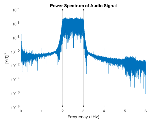
The figure above shows the response curve of the filter. This was generated by passing random white noise into the filter, converting it to audio and capturing via a PC sound card and FFTing in Matlab.